See for more themes.
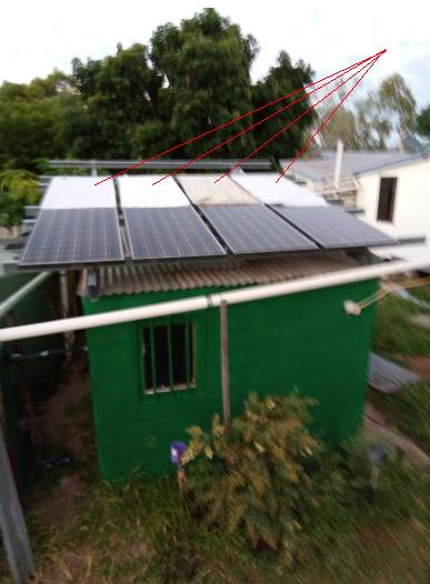
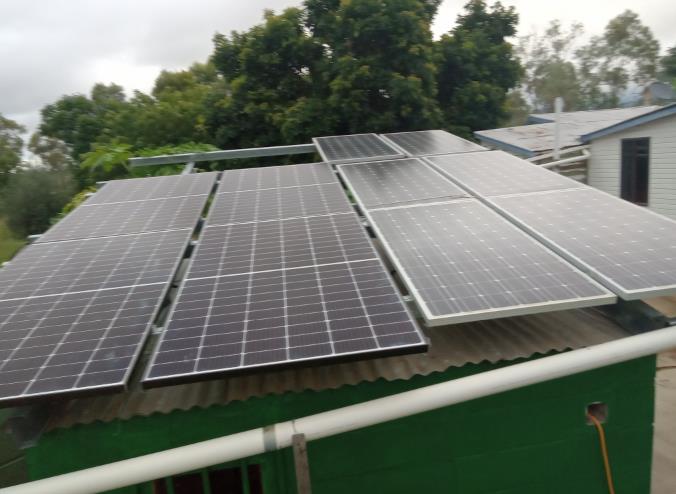
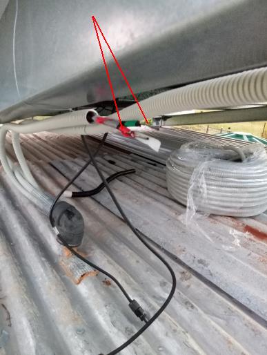
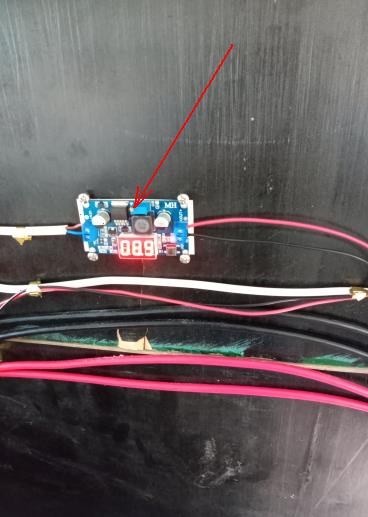
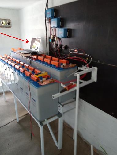
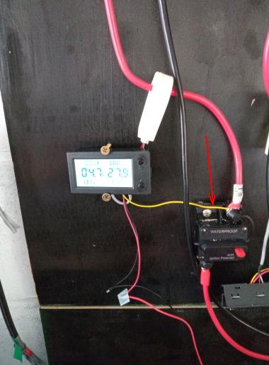
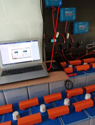
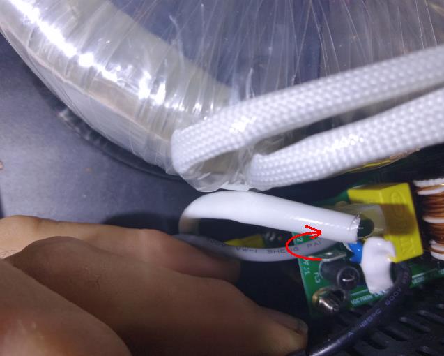
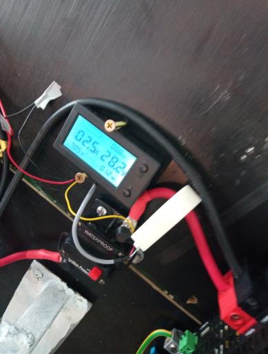
 | Q9: Off Grid - wiring inverter Notice blankets on the second array of panels. Notice the remake over with new solar panels. The second string, the Zeus-Apollo are six panels all connected in parallel. The first string , the Trina Sola, are four panels connected two in series and two in parallel. Crimp connections, heat wrap, and wire away from mice and rain. Here in red arrow are the color coded wires in conduit. Add the DC to DC convertor, to drive ammeters (they need 9VDC). Adjust output voltage by turning potentimeter. (red arrow) Like so, red arrow shows computer to interface MPTT, via a VE direct USB cable. But not working as yet. No device found. The halls effect ammeters, Red wire is 9V, black wire is return to DC converter. Yellow wire to the cable being tested. Not happy with the ammeter readings, mostly 2 to 5 amps, too low for my liking, but perhaps this is because the MPTT folds back charging as the voltage rises to fully charged. I will leave these older comments here, just to show you experience and learning. Could not get the device to connect to computer. Bother. Tried uninstall and install software again. Discovered one needs to reinstall the device driver. Next, made lugs and 50Amp fuse holder for the first Inverter. Opened up inverter and removed power point (should not have one on inverter). Added lugs and crimped, heat wrap, to extend wires through grommet to external appliances such as RCD and CB. The RCD tried is type A, $26 dollars. The CB is harder to source from the USA for $14 , a 4.0 amp CB, to reduce overload of circuit to just 920Watts.
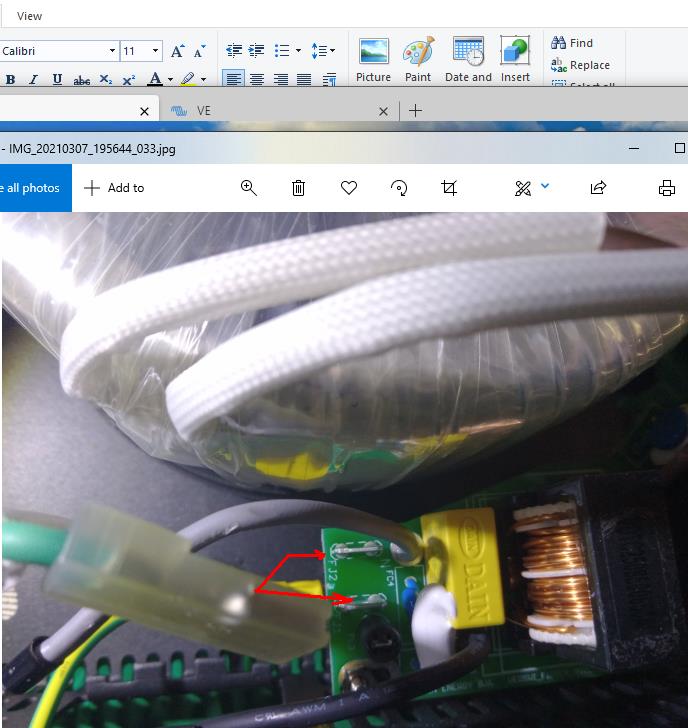
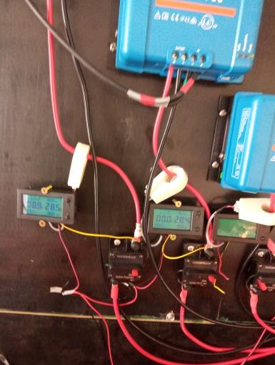
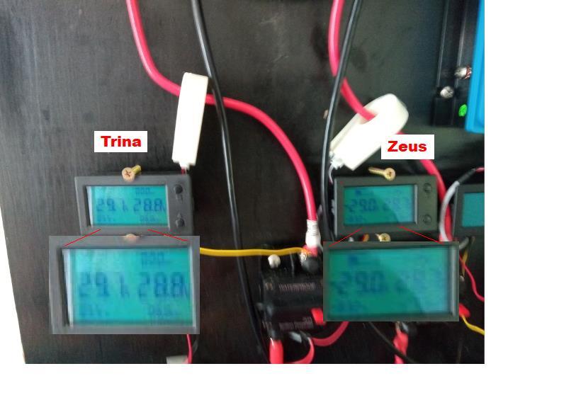
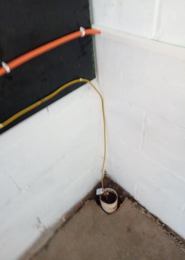
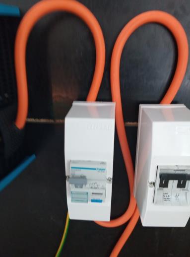
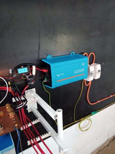
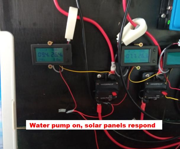
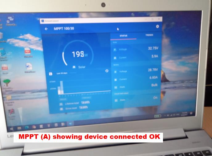
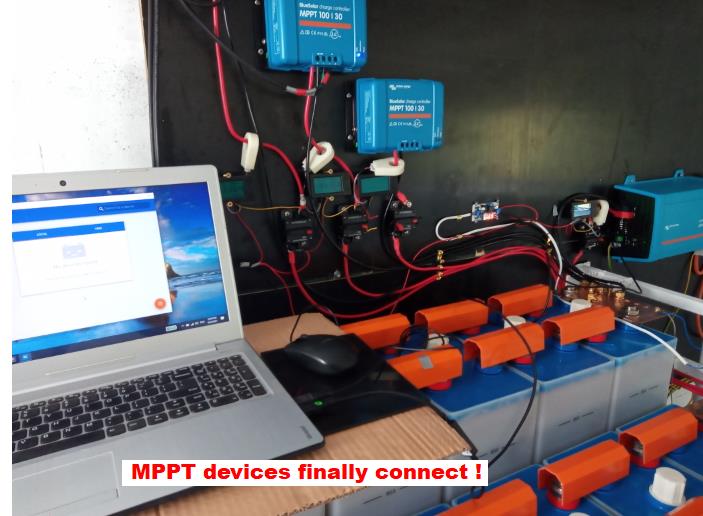
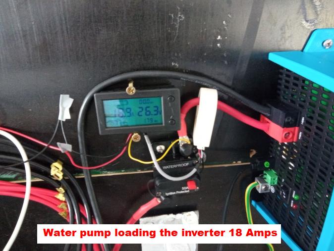
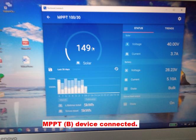
Installed earth stake and earth wires to inverter. Hooked up inverter and switched it on, to check active and neutral wires. Discovered both wires are alive. Not safe. Some cheap appliance for camping equipment I suspect, should not be allowed in Australia. After 2 hours reading, mucking around with Victron, manuals, not much help, discovered this forum solution hidden away. Here is the problem, with transformers not earthed with output terminals, Remove the earth wire from your Phoenix 1200VA Victron Inverter (see red arrows) Like so and place on the other jumper, supplied by Victron, which funny enough is not the standard default for selling these products to A ustralian wiring standards. Now when you test your Inverter, the output wires have one active wire and one neutral wire, as per normal Australian mains power supply, One can now proceed to RCD and CB switches. Now MPTT (1) and MPPT (2) are both running, supplying 5 and 6 amps respectively. I show older pictures of older not functional solar charging for experience. The system rebuild is working much better now ! with new Trina panels, $1,200 Installed new earth stake into corner of building, with aim to add water every so often. Remember the building as a dirt floor with carpet laid over the ground. Images of the Residual Circuit Breaker (safety switch) Type A Australian design, and Circuit Breaker (4.0 amps) from the USA. Notice the earth wire is joined to the netural wire, before the RCD uses the circuit wires. The inverter is tested with a 60W light bulb, such a appliance has the Inverter drawing 2.5A to run the light bulb and itself with 98% efficiency. The view of the first inverter so far. There is a earth ground wire on the Inverter, and a earth wire before the RCD, joining unto the neutral wire, as well the earth wires run back into the Inverter, grounding the chassis and transformer internally. After the RCD, no further earth wires should occur. The view of the whole system so far, two Victron 100/30 MPPT's are running, and one Victron Phoenix 24/1200VA is running so far. Next we test the Inverter with a water pump. The Incoming currents show 9 and 7 Amps respectively, the voltage drops to 26 V. Next the computer connects to the first MPPT (1). It shows 198 Watts coming in, with 4 Amps charging. The default setting for the charging programme is "2". And this seems OK for now for Ni-Fe batteries. My Battery Supplier told me to change these to user defined setting The water pump draws 18 Amps from the batteries. The second MPPT (2) is getting 149 Watts, and delivering 5 amps to the batteries. Next we test the system for a solid week, before adding more loads.
|
Created by Rob Thompson. Hosted since 10/01/2012. Visitors HOSTED by Prologic, my Son. A thin website.