See for more themes.
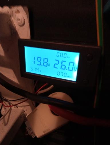
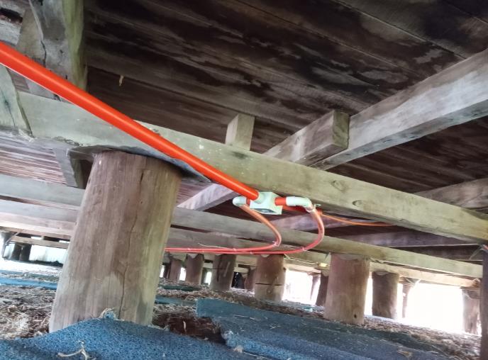
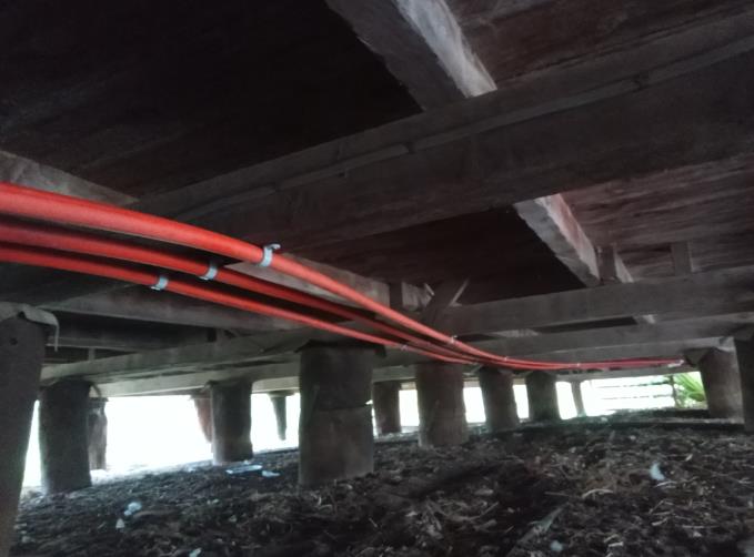
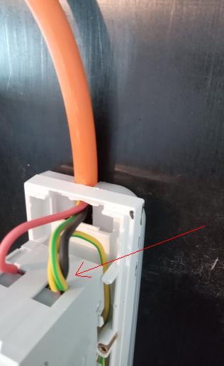
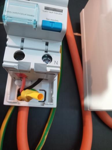
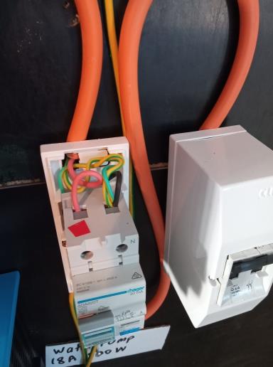
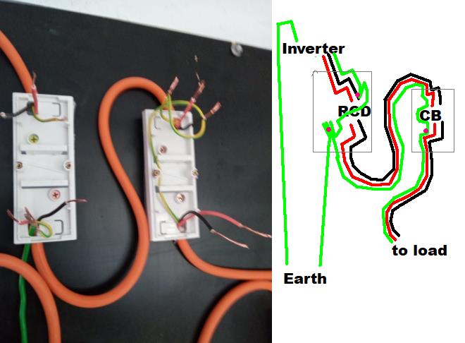
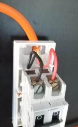
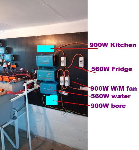
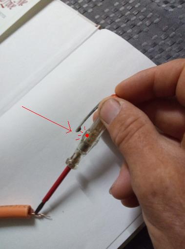
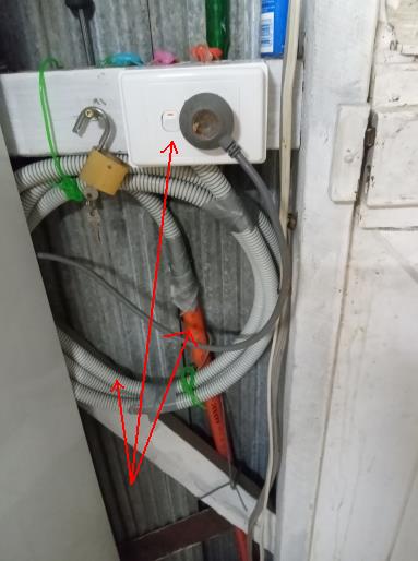
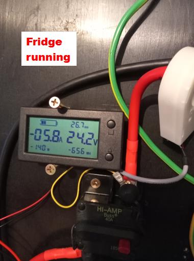
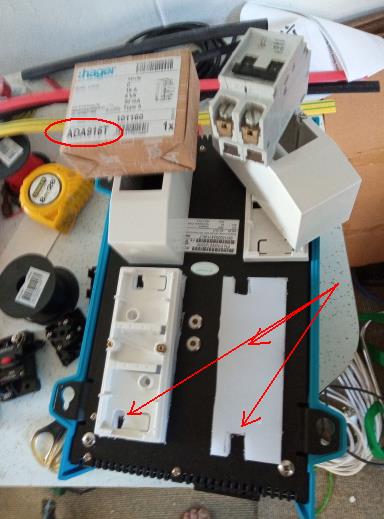
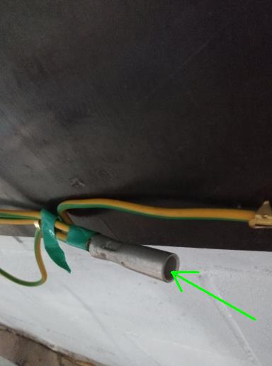
 | Q11: Off Grid - Adding more inverters After a solid week running the water pump, we can add more inverters. At least now we get 60 Amps charging on sunny days. Notice the pump uses 514Watts, draws 20 Amps, the Bank is 26Volts, about 80% full. These halls effect ammeters are cheap and great for information. Leaving the back lit off, (forget about settings) you have each running on 15milliamps. So I purchased heaps of them ($200 worth) to show display for all the things going in and going out. I am a visual person, like lots of display to monitor what my systems are doing, continueously. This is far more detailed monitoring of your system, than the Victron BMV 712 monitor, which is a lot of hype. However the Victron BMV 712 monitor does help calculate the discharge into and out of your battery, which is helpful. I discuss this later in my webpages. Back under the house, I drilled holes in floor for conduit to each powerpoint, and added the three pipes leading towards kitchen/ laundry. Notice the third conduit goes to a powerpoint, and back under the house to another powerpoint elsewhere as a shared load. Normally one line receives one powerpoint. But with shared lines one has to watch you loading of the line, each line can only handle 900Watts. Off grid is usually doing with less power than mains power, where each line is rated to 15 amps. In off grid here on L500 amp hour batteries, the lines are limited to 4 amps only. The ADA RCD Residual Circuit Breaker has the earth wire joining the neutral wire. Notice two earth wires, one goes into the beginning of the RCD, the other feeds the exit of your cables, leaving the RCD. Like so. Bit hard to see the earth wire , a big 4mm2 wire comes in, and 1.5mm2 earth wires for the orange cable. The earth is crimped and yellow heat shrink tube added. A picture of my older RCD showing the wiring as well, notice the red tape to indicate active end. A picture of the RCD and CB, with wiring diagram. Always be careful and double check your progress. The double pole 4.0 amp Circuit Breaker. In hindsight, purchasing a 3.5 amp CB, or even a 3.0 amp CB, might be better. Or better still purchase 1500 VA inverters, and limit the output of your inverter to 1000 watts with the 4.0 Amp CB, which really trips at around 5 amps, say. I shyed away from getting bigger Inverters, because they draw too much current, and place strain on battery chemistry. Drawing say 60 amps from your bank, leads off down two rails into 20mm nickel posts, nickel is a poor conductor, and each cell is drawing 3 amps only, about 1.5 amps from each post. In practice, the cell closest to the postive gets the biggest strain, and the others less, and the impedance affects each cell along the rails. So each post gives a little, and is charged a little. That is how Nickel-Iron works. How the system look so far. Old picture (updated to 930W inverters. Why? because over time your motors age, drawing more current. As your battery voltage decreases, the motors draw more current, so getting a bigger Inverter in better. ) The fridge is now connected to the bank for the first time. Suprisingly our old current fridge works happily on less than 560W, and when on draw 4 amps using 150W of power. These figures refer to the bank power side, not the fridge power side. These hall effect meters also handle up to 240 AC I believe?, so you could hook one up on the Invertor side leading to your appliance. So this means the fridge is using for theory calculations: 0.6 amps @240V = 150W Watts = Volts times Amps When I tested my Fridge Inverter for the first time, it gurgled noise and red alarm LED came on. Hmm? overload. But why? All the wires are OK, red to red, black to black, nothing is plugged in. I suspected the active was running into earth, so removed wires from RCD and tested using my 240AC tester. A must for 240V, a cheap $3 screwdriver with massive resistor you touch with finger, and LED glows if wire is alive. Sure enough my faithful AC tester said the Black neutral was active and the Red active was nothing. Such a 240V Tester is a must for all 240V work, never assume a wire, is dead or alive. The manufacturers have grey and black wires inside the inverter, so its a guess as to which is active. The previous Invertor I tested said Grey wire is active, but never assume. Rather than rewire my leads, I swapped the wires over, taped them correct colours and tested the Invertor. It was fine, a green LED indicating ready for loads. Such errors help readers experience. The kitchen fridge, such an old farm house, over 100yrs old. The orange conduit has excess wiring, and is wrapped around flexible conduit, and NOT cut or removed, as I have plans to upgrade this kitchen room with a new one. The old 240Volt fridge happily runs fine, saving us having to purchase a new one yet. The fridge is running, using 6 amps and 140 watts, rather cheap really. It has it's own inverter, 800VA and power line. The most power hungry power appliance is the water pump, 520 watts using 20 amps when running. The Inverter got hot today running 6 hours pumping water. I suggest giving the Inverter/water pump a rest, say 2 hours in the morning and 3 hours in the afternoon. The panels require lifting off board for wires to enter from under the panel cover plates, so I cut plastic chopping boards ( 8 mm thick) for holding the orange cord, and for entry underneath the panel covers. The picture shows all the items required. One advantage with my style of crimping is the other open end can be left on for future expansion for more wires. In this case I added more earth wires for more invertors. Next we look at maintenance of the electrolyte of the batteries.
|
Created by Rob Thompson. Hosted since 10/01/2012. Visitors HOSTED by Prologic, my Son. A thin website.