See for more themes.
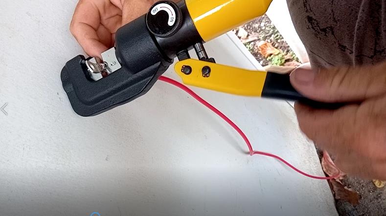
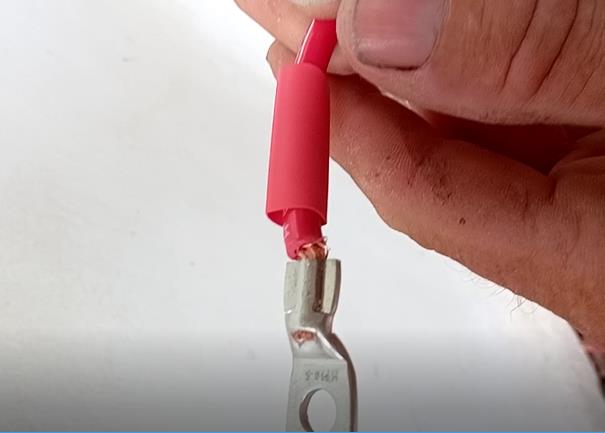
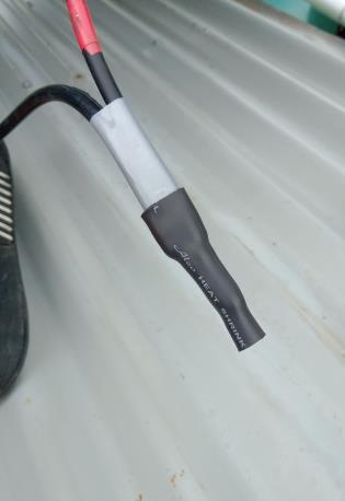
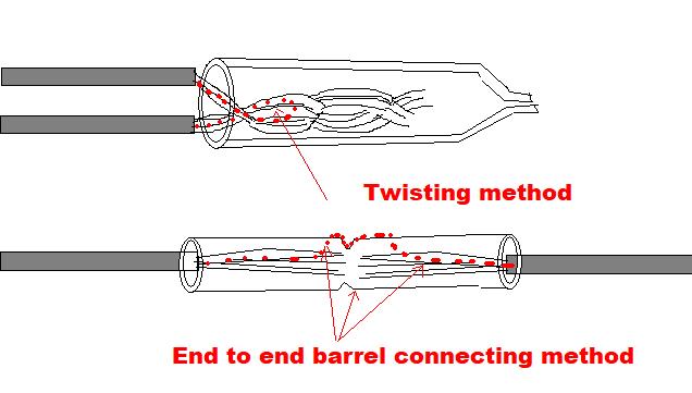
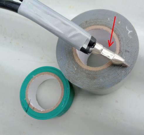
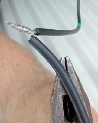
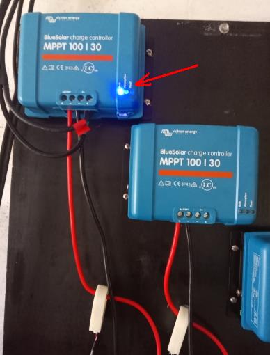
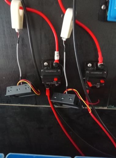
 | Q8: Off Grid - wiring solar panels Here is a picture of crimping as a process using hand tool. Notice close up of the crimp, before heat shrink applied. My own personal style of crimping wires together, rather than use a barrel connector, I twist the wires together and place a crimp over them, crimping them together as one mass of copper.While the wires look ugly, this is a better electrical connection than a barrel end to end connection, which has three electrical interfaces rather than one, as mine method does. This process is standard in the electrical industry for adding wires together. Consider the electrical diagram below: With the twisting method, the current flows directly into the twisted mass of the other wire (s) directly. One interface of copper impedance. With the end to end barrel connection, the current flows over three impedance surfaces, may look neater, but if a poor crimp ensures, leads to more electrical impedance than twisting the wires together.This is especially true if the current load increases. Notice the crimp using this sytle. The barrel connector is broken off, giving you two connectors for the price of one. Red arrow shows the crimp indentation. The electrical pliers twist the end together, before crimp forces the twisting into a single mass of copper. Connect the battery power to MPPT first, to lock in it's voltage at 24 volts. Than connect the wires from your first "string array of solar panels". Remove blankets from roof, and the bulk LED light comes on, showing the charging of the batteries. The adjustable float voltages are not much different, most 27 Volts, and the rotary switch is in a silly place. So I purchased a VE Victron USB cable ($50) to connect to each MPTT and select the best float voltage. But for now, the system is working crudely, but OK. Picture of the re-settable fuses, rated at 30Amps. Also the ammeters, not connected up as yet. These are hall effect ammeters, that run off 5V, for measuring current flow.
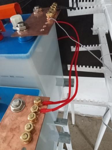
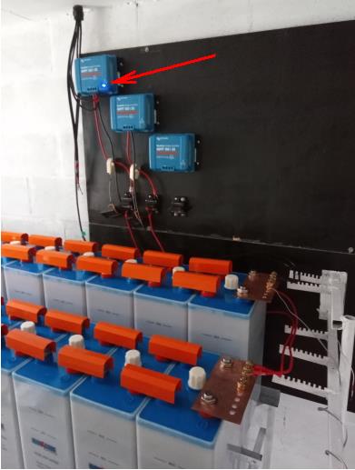
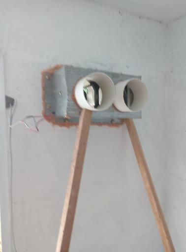
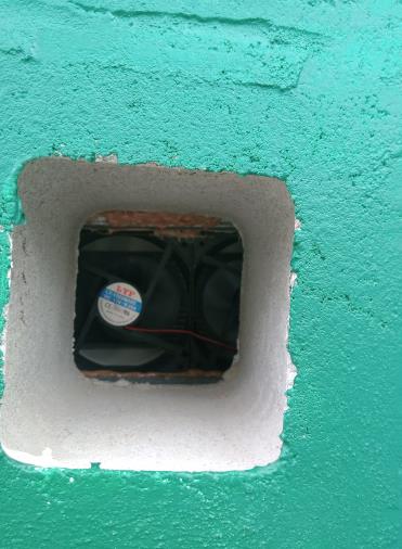
The first of wires going into wire track onto the copper rails. How the system looks so far, notice red arrow shows first MPTT is working OK, the bank of cells gurgle H2 gas from the electrolyte. Wires require neater attachment, to be done later. Next glue, screw, make metal fan extractors. I use 2 computer fans, thus 2 x 12VDC = 24VDC fan system. This gives the banks something mild to do, while the system settles down, the chemistry of the voltages is not quite right.The full charging process will take a week at this rate of 25amphours per hour. That is roughly 100 amp hours per day. The air is whizzing outside the hole in the wall. This small 24hours, 7 days / week fan is used to remove humidity from room, and H2 gas from each cell. Plus allows a small discharging at night from bank, to get system settled into charging and discharging. Next we continue looking at system and add our first major invertor.
|
Created by Rob Thompson. Hosted since 10/01/2012. Visitors HOSTED by Prologic, my Son. A thin website.